Read more
Alternatives to Switch Stacking in Enterprise Networks:Asterfusion Cloud Cluster
Switch Stacking in Enterprise & SMBs Networks
In traditional enterprise networks, enterprises and vendors build the network architecture by using fixed configuration switches and modular chassis systems. When they realized that in some scenarios, modular chassis systems are too expensive and not so flexible, while independent fixed configuration switches are not easy to manage, stacked architecture was introduced for the following considerations:
- Simplified management: After established, the stack of switches can be considered as a logical entity with a single management interface, which makes management and operation very easy.
- High availability: The stacking system can provide link aggregation between ports of different physical switches, which has better bandwidth and resiliency for the downlinks. Working as a logical switch, the stacking system has no need for traditional loop avoidance protocols.
- Flexible expansion: Compared to modular chassis, stackable switches provide a less expensive option for especially SMB cases, but with a similar scalability and “pay as you grow” flexibility.
Drawbacks of Switch Stacking in Next-gen Enterprise Network
The advantages of stacked architecture which was introduced in 1990s are still very important nowadays, but as the wired, wireless and IoT devices are growing fast, traditional stack architectures are facing several drawbacks to the next-generation enterprise network:
- Inherent limitations: Stacking is not a standard protocol, different vendors use different cables, connectors and software in their stackable switches, and even different switches from the same vendor cannot be stacked. If the switches in the stacking system are at the end of marketing, the entire stacking system must be replaced for expansion.
- Limited bandwidth: Most vendors limit the number of stack members due to the stacking bandwidth limitation. Moreover, it is confusing that vendors have different ways to report stacking bandwidth. For example, some vendors count stacking bandwidth separately for each direction, which may mislead the customers to believe they have twice as much bandwidth as they actually have.
- Stack split: Expanding or removing a stack member could cause a service interruption because the process requires a reboot of all the stack members. When failure or wrong operation happens, the stack may be divided into 2 or more stacks.
- Software impact: Running the stack will add a lot of complexity to the software (stack management, split detection, etc.). In reality, a stack is fate-sharing, software issues may cause the entire stack failure.
- Physical topology limitation: For timing requirement of the control plane and bandwidth consideration, stackable switches use proprietary stacking cables, which limit the distance and topology of stack members into one room or even one cabinet.
Asterfusion’s Cloud Cluster Solution for Enterprise Network – Spine/Leaf architecture
In the initial stage of cloud computing development, the cloud network architecture was built with reference to the traditional campus network. Driven by market demand and technological progress, the cloud network has undergone 20 years of transformation and sublimation. Its development has far surpassed the traditional ones—whether it is the overall network architecture or in terms of hardware equipment, scalability, and operation and maintenance capabilities, cloud networks are more advanced than traditional ones.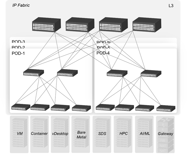
Figure 1 A Mainstream Cloud Network Architecture
Today, Asterfusion has introduced cloud-based open architecture back to the enterprise network. The CLOS based Spine-Leaf architecture retains the advantages of stacking ones and can also solve some drawbacks of them.
Comparison between Switch Stacking and Asterfusion Cloud Cluster
Now we can make a simple comparison between stacking architecture and cloud cluster in terms of deployment and O&M aspects. The obvious advantages of cloud clusters are bold marked:
| Stacking | Cloud Cluster | |
|---|---|---|
| Deployment | 1. Stacking cable connection (or service ports connection with stacking configuration) 2. Enhanced configuration (split detection, load-balance mode) | 1. Cable connection between spine and leaf layer 2. Configure loopback interfaces and BGP peers |
| High availability | Link aggregation between physical devices | All layer 3 network with BGP and ECMP |
| Physical topology | Limited into one room or cabinet | No physical limitation |
| Management | Stacking group as a logical device | Each layer as a logical device |
| Software upgrade | Need stacking group reboot with service interruption | Upgrade each device separately without interruption |
| Expansion | Need to design based on current topology (chain or ring) | Standard CLOS architecture expansion |
| Access Scalability (48-port switch as example) | Maximum stacking member number is 8 as an example: maximum 8 x 48 = 384 access ports | 2-layer CLOS: maximum 48 x 48 = 2304 access ports 3-layer CLOS: maximum 48 x 48 x 64 = 147456 access ports (using 64 ports switch as layer-3 CLOS spine) |
Simplicity and Flexibility
After the interconnection and registration configurations finish, the cloud cluster is established and the switches working in the same layer will work as a logical switch with a unified management interface (just like stacked systems), the configuration will be synchronized automatically to the cluster members.
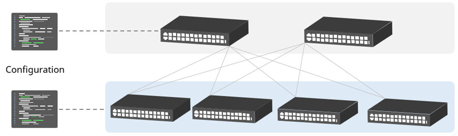
Figure 2 Each Layer as a Logical Device
When new members added to the cluster, only registration work is necessary. Due to the Spine-Leaf architecture, the scale of the cluster can be very large without worry about stacking bandwidth. For example, in a stacking system of 48-port access switch, the maximum number of downlink ports is 48×8 (stack member limitation), but in cloud cluster, the number can be easily extended to 48×48, even 48x48x64 in a 3-layer CLOS architecture.
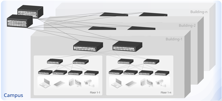
Figure 3 Scalable Multi-layer CLOS Architecture
Further Consideration of Cloud Cluster Solution in Enterprise Network
In traditional layer-2 enterprise network, many complicated features are deployed to avoid the risks such as ethernet loop and broadcast storm. Asterfusion cloud cluster adopts all layer-3 networks to naturally avoid the above risks. Moreover, compared with the layer-2 network running STP, it can make full use of the network resource.
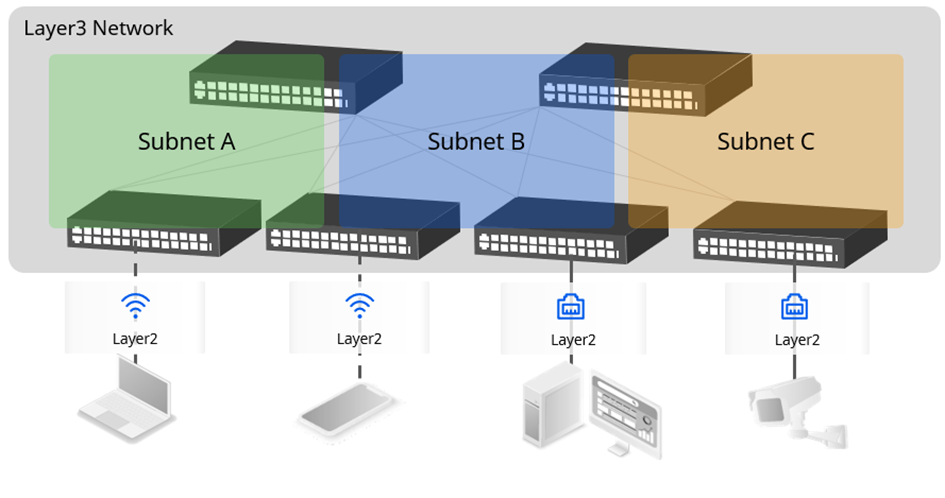
Figure 4 Layer-3 IP Fabric
For simplicity consideration, cloud cluster adopts unified BGP instead of complex IGP+EGP structure. MP-BGP or EVPN is used to synchronize the routing information between different subnets and distributed gateways. Using the ECMP load sharing capability of the layer3 network, all the bandwidth between switches can be fully utilized to transmit packets, making the network performance higher.
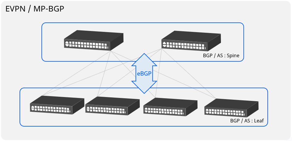
Figure 5 Unified BGP Routing
For more information, visit: https://asterfusion.com/enterprise_network/ or send email to sales@asterfusion.com
